
How to Size Drainage Trench Grating
Start with the clear opening and load case, then define the support seat, bearing-bar direction, panel joints, handling size, drainage opening and restraint. A trench width alone is not enough for manufacture.
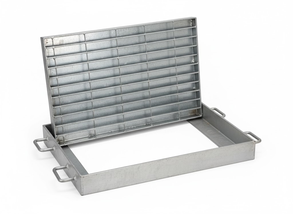
1. Record the trench geometry
Show the clear opening, total channel width, frame profile, finished level, corner geometry and any changes in direction. Record whether the dimensions are design values or verified site measurements. Existing concrete channels often vary, so a survey may be needed before fabrication.
2. Separate clear span from cover size
The structural span is the unsupported distance between seats. The manufactured panel must also have adequate bearing at both ends while allowing realistic installation clearance. Do not order a cover at exactly the clear-opening width without confirming the frame and seat arrangement.
3. Put the bearing bars in the correct direction
The bearing bars are the deeper primary bars. They should span from one support seat to the other, normally across the trench. The cross bars hold spacing and transfer local effects but are not a substitute for primary supports. Mark bearing-bar direction on the drawing.
4. Define the design load
State whether the area is pedestrian-only, maintenance access, pallet-truck, forklift, road vehicle or another condition. For wheels, provide wheel load, contact area, axle arrangement, impact allowance and possible travel path. The responsible engineer should define the load combination and allowable deflection.
5. Check drainage and opening limits
Open area affects water flow, debris passage and cleaning. Mesh also affects footwear, small-object retention and accessibility. If the project has a maximum clear opening or ball-proof requirement, state it explicitly instead of relying on a generic product description.
6. Choose manageable panel lengths
Long panels reduce joints but can be heavy and awkward to remove. Divide continuous trenches around safe lifting weight, access points, changes in direction and support locations. Identify every panel with a mark that matches the layout drawing.
7. Complete the frame and restraint details
Check seat width, frame stiffness, anchorage, rocking prevention, uplift restraint and anti-theft requirements. Traffic areas may require positive restraint and a frame engineered for repeated wheel loading. Avoid creating an unsupported cut edge at outlets or intersections.
Information to send with an RFQ
- Plan and section showing clear opening and frame.
- Design load, contact area, span and deflection criteria.
- Material, finish, mesh and surface requirement.
- Panelization, lifting limits, fixing and piece marks.
- Quantity, inspection documents and delivery destination.
Frequently asked questions
Should bearing bars run along the trench?
Normally no. They usually span across the shorter clear opening between the two side supports.
Can one bar size cover every trench on a project?
Only if every span and load case has been verified. Wider openings and heavier traffic may require a different section or support arrangement.
Who confirms the final load capacity?
The responsible project engineer should approve the load case, support condition, product selection and complete assembly.
Send a trench plan, section and load case for a manufacturer quotation.