
Trench Cover Design: Verify the Complete Load Path
A trench cover is not a loose panel with a traffic label. Its performance depends on how the surface receives load, how bearing bars and edge bands move that load to the seat, how the frame distributes reaction and how anchors and restraint keep the assembly stable.
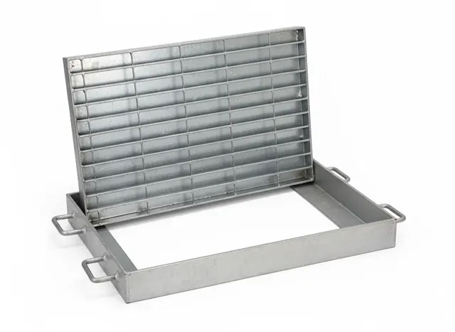
Start with the operating zone
State whether the trench is in a restricted maintenance area, process drainage zone, pedestrian route, loading bay, forklift path or road-vehicle lane. Include abnormal but credible access such as fire or heavy maintenance vehicles. Traffic class names alone are not enough unless their scope and test basis match the complete assembly being supplied.
Separate uniform and concentrated loads
A uniform load spreads across the panel. A wheel or point load enters through a limited contact patch and may govern local bearing bars, edge bands, panel joints and frame deformation. Provide maximum wheel force, tire or wheel footprint, axle arrangement, travel path, speed, impact, braking, turning and crossing frequency.
The wheel path matters: a load crossing near an unsupported panel end can be more severe than the same wheel near a continuous support line.
Freeze the real clear span and seat
Measure the clear distance between bearing seats and identify the direction in which bearing bars span. Record seat width, level tolerance, frame continuity and any gaps required for drainage or debris. A stiff panel on an uneven or undersized seat can rock, crush an edge or transfer load unpredictably.
Detail panel ends and joints
End banding stabilizes bearing-bar ends and improves handling. A load-carrying band or dedicated joint support may be needed where wheels cross a panel end. Panel joints should be placed over support wherever practical, with gaps controlled to limit rocking, noise and debris traps.
Design the frame, anchors and restraint
Choose an angle, channel or beam frame around support stiffness and construction interface—not only a convenient stock size. Anchors must suit concrete or steel substrate, edge distance, corrosion exposure and installation tolerance. Restraint can range from bolts and clips to hinges, recessed keys or anti-theft details, selected around traffic, uplift, security and access frequency.
Plan removal and installation
Split long trenches into repeatable modules that can be handled safely. Set a panel weight limit, identify lifting points or tools and mark installation sequence and bearing direction. Survey the trench, set and brace the frame, install anchors or grout to the approved detail, then verify seating and every restraint before opening the route.
Send a complete engineering package
Provide plan and sections, opening geometry, support substrate, operating zone, load data, environment, drainage, access frequency, security needs, material and finish. Download the 2026 Trench Cover & Heavy-Duty Systems Guide for the full assembly checklist.
Frequently asked questions
Can a grating load table size a vehicle-duty trench cover by itself?
No. A table can screen the bearing bars, but vehicle duty also requires checks of wheel footprint, panel ends, joints, frame, anchors, restraint and the actual support geometry.
Why do trench cover panels rock after installation?
Common causes include uneven seats, tolerance buildup, unsupported joints, missing restraint or frame deformation. The panel and frame need to be inspected as an assembly.
What should be shown for removable covers?
Show module size and weight, bearing direction, lifting points or tools, sequence marks, joints, supports and the selected locking or hold-down method.