Press-welded steel bar grating — specifications, common models, and full YB/T 4001.1 Appendix E load & deflection tables for flat bar (30 / 40 / 20 mm pitch), I-bar, and heavy-duty series.
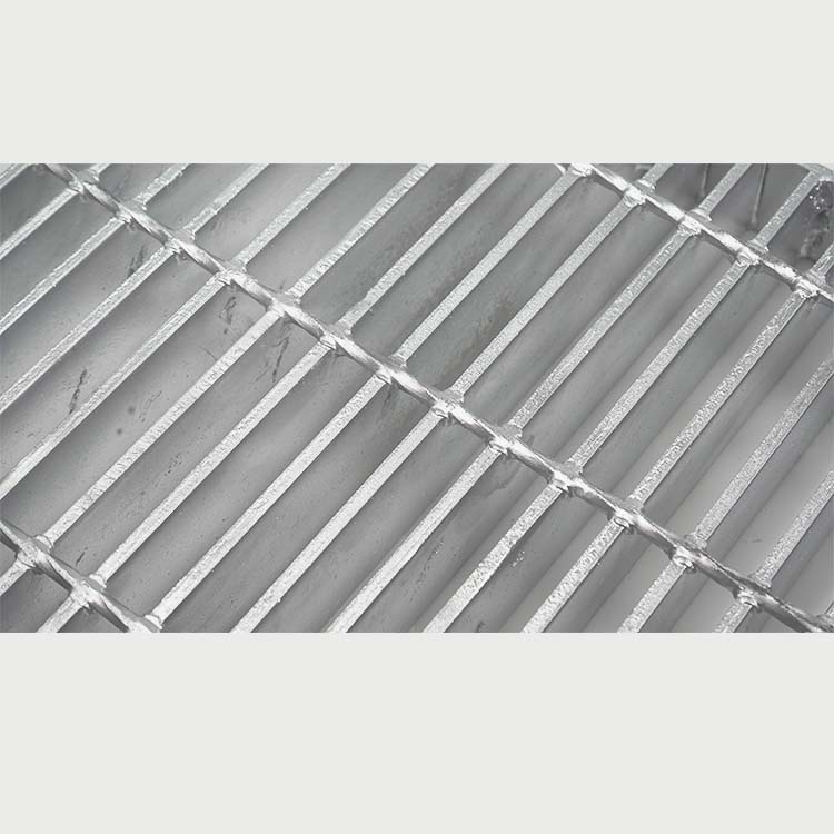
Crossing detail — forge weld at each intersection.
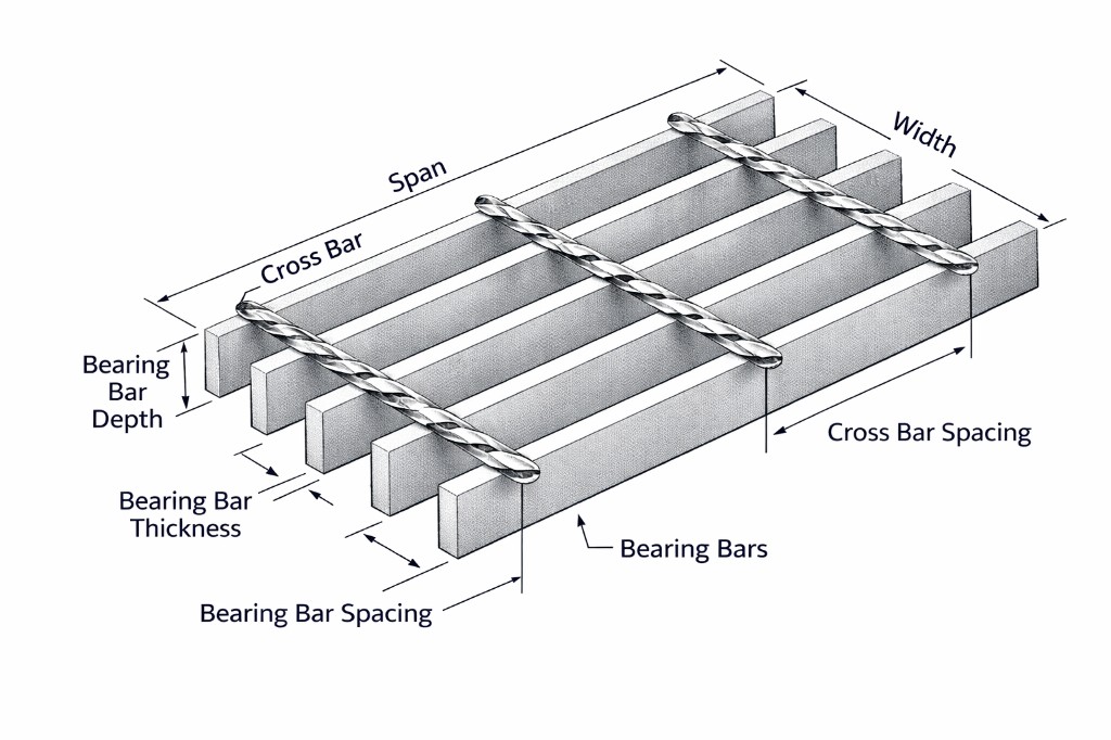
Press-welded (electro-forged) steel bar grating: bearing bars and twisted square cross bars are resistance-welded at every intersection under approximately 1,000 kN forge pressure. The result is a permanently fused grid with high structural integrity, open area for ventilation, light and drainage, and predictable load paths for engineering design.
Technical specifications
Parameter
Range / description
Construction
Press-welded (electro-forged) at every crossing
Material
Carbon steel Q235B / A36 / S235JR (stainless on request)
W-30-100, 30×5, Q235B, Serrated, Hot-Dip Galvanized — welded, 30 mm bar pitch, 100 mm cross pitch, 30×5 mm bearing bar, carbon steel, serrated, HDG. YB/T model codes (e.g. G305/30/100W) may also be used.
Common models
Approximate weights for untreated, unbanded panels. HDG adds ~5–10%. T = twisted square cross bar. Ball = heel-proof clear opening.
Model
H mm
T mm
s₁
s₂
Cross
kg/m²
Open %
Ball
Use
WA253-30100
25
3
30
100
6T
~18
83
—
Standard
WA255-30100
25
5
30
100
6T
~26
82
—
General
WA305-30100
30
5
30
100
6T
~30
81
—
General
WA305-3050
30
5
30
50
6T
~34
75
35 mm
Close mesh
WA305-2050
30
5
20
50
6T
~45
65
20 mm
Pedestrian
WA325-30100
32
5
30
100
6T
~33
81
—
General
WA405-30100
40
5
30
100
6T
~39
80
—
Medium
WA505-30100
50
5
30
100
6T
~48
79
—
Heavy
WA605-30100
60
5
30
100
6T
~57
78
—
Heavy
WA305-40100
30
5
40
100
6T
~21
85
—
Economy
WA255-40100
25
5
40
100
6T
~19
86
—
Light
WA305-50100
30
5
50
100
6T
~17
88
—
Open
WA405-3050
40
5
30
50
6T
~44
74
35 mm
Cover
WA505-3050
50
5
30
50
6T
~54
72
35 mm
HD Cover
Design notes
Simply supported: All tables below assume simply supported spans perpendicular to bearing bars. Span range: 200–3000 mm in 200 mm steps.
U vs C:U tables are for 50 mm cross-bar pitch (uniform load, kN/m²). C tables are for 100 mm cross-bar pitch (line load, kN/m). This follows YB/T Appendix E conventions.
Safe loads: Values are safe working loads extracted from YB/T 4001.1-2007 Appendix E — they do not include national partial safety factors. Request stamped calculation sheets for code compliance.
Deflection: Typical limit is span/200 or stricter (owner specification governs). Serrated bars reduce effective depth slightly.
Installation: Welded or clip-fixed. Removable grating per YB/T requires minimum 4 clips per panel. See Installation and Fixings.
Panel width by bar count (E.7)
Nominal panel widths in mm, based on bearing bar count and pitch, per YB/T 4001.1 Appendix E.7. Two columns per pitch: t ≈ 3 mm and t ≈ 5 mm bar thickness.
30 mm pitch
Bars
t ≈ 3
t ≈ 5
8
213
215
9
243
245
10
273
275
11
303
305
12
333
335
13
363
365
14
393
395
15
423
425
16
453
455
17
483
485
18
513
515
19
543
545
20
573
575
21
603
605
22
633
635
23
663
665
24
693
695
25
723
725
26
753
755
27
783
785
28
813
815
29
843
845
30
873
875
31
903
905
32
933
935
33
963
965
34
993
995
40 mm pitch
Bars
t ≈ 3
t ≈ 5
4
123
125
5
163
165
6
203
205
7
243
245
8
283
285
9
323
325
10
363
365
11
403
405
12
443
445
13
483
485
14
523
525
15
563
565
16
603
605
17
643
645
18
683
685
19
723
725
20
763
765
21
803
805
22
843
845
23
883
885
24
923
925
25
963
965
26
1003
1005
20 mm pitch
Bars
t ≈ 3
t ≈ 5
10
183
185
11
203
205
12
223
225
13
243
245
14
263
265
15
283
285
16
303
305
17
323
325
18
343
345
19
363
365
20
383
385
21
403
405
22
423
425
23
443
445
24
463
465
25
483
485
26
503
505
27
523
525
28
543
545
29
563
565
30
583
585
31
603
605
32
623
625
33
643
645
34
663
665
35
683
685
36
703
705
37
723
725
38
743
745
39
763
765
40
783
785
41
803
805
42
823
825
43
843
845
44
863
865
45
883
885
46
903
905
47
923
925
48
943
945
49
963
965
50
983
985
51
1003
1005
Load & deflection tables (YB/T 4001.1 Appendix E)
Spans in mm (column headers): 200, 400, 600, 800, 1000, 1200, 1400, 1600, 1800, 2000, 2200, 2400, 2600, 2800, 3000. Bearing bar noted as depth × thickness (mm). "—" = beyond usable range for that bar size. Values from master-data1.js; reference only — verify on released submittals.
E.1 — 30 mm pitch · 50 mm cross · Uniform load U (kN/m²)
Bearing bar
200
400
600
800
1000
1200
1400
1600
1800
2000
2200
2400
2600
2800
3000
65×5
39.9
10.0
4.4
2.5
1.6
1.1
0.8
0.6
0.5
0.4
0.3
0.3
0.2
0.2
0.2
60×5
34
8.5
3.8
2.1
1.4
0.9
0.7
0.5
0.4
0.3
0.3
0.2
0.2
0.2
—
55×5
28.6
7.1
3.2
1.8
1.1
0.8
0.6
0.4
0.3
0.3
0.2
0.2
0.2
—
—
50×5
23.6
5.9
2.6
1.5
0.9
0.7
0.5
0.4
0.3
0.2
0.2
0.2
—
—
—
50×3
14.2
3.5
1.6
0.9
0.6
0.4
0.3
0.2
0.2
0.1
0.1
—
—
—
—
45×5
19.1
4.8
2.1
1.2
0.8
0.5
0.4
0.3
0.2
0.2
0.1
—
—
—
—
40×5
15.1
3.8
1.7
0.9
0.6
0.4
0.3
0.2
0.2
0.1
—
—
—
—
—
40×3
9.1
2.3
1
0.6
0.4
0.3
0.2
0.1
0.1
—
—
—
—
—
—
35×5
11.6
2.9
1.3
0.7
0.5
0.3
0.2
0.2
0.1
—
—
—
—
—
—
35×3
6.9
1.7
0.8
0.4
0.3
0.2
0.1
0.1
—
—
—
—
—
—
—
32×5
9.7
2.4
1.1
0.6
0.4
0.3
0.2
0.1
0.1
—
—
—
—
—
—
32×3
5.8
1.4
0.6
0.4
0.2
0.2
0.1
0.1
—
—
—
—
—
—
—
25×5
5.9
1.5
0.7
0.4
0.2
0.2
0.1
—
—
—
—
—
—
—
—
25×3
3.5
0.9
0.4
0.2
0.1
0.1
—
—
—
—
—
—
—
—
—
20×5
3.8
0.9
0.4
0.2
0.1
0.1
—
—
—
—
—
—
—
—
—
20×3
2.3
0.6
0.3
0.1
0.1
—
—
—
—
—
—
—
—
—
—
E.1 — 30 mm pitch · 100 mm cross · Line load C (kN/m)
Bearing bar
200
400
600
800
1000
1200
1400
1600
1800
2000
2200
2400
2600
2800
3000
65×5
4.0
2.0
1.3
1.0
0.8
0.7
0.6
0.5
0.4
0.4
0.4
0.3
0.3
0.3
0.3
60×5
3.4
1.7
1.1
0.8
0.7
0.6
0.5
0.4
0.4
0.3
0.3
0.3
0.3
0.2
—
55×5
2.9
1.4
0.9
0.7
0.6
0.5
0.4
0.3
0.3
0.3
0.3
0.2
0.2
—
—
50×5
2.4
1.2
0.8
0.6
0.5
0.4
0.3
0.3
0.3
0.2
0.2
0.2
—
—
—
50×3
1.4
0.7
0.5
0.3
0.3
0.2
0.2
0.2
0.1
0.1
0.1
—
—
—
—
45×5
1.9
0.9
0.6
0.5
0.4
0.3
0.3
0.2
0.2
0.2
0.2
—
—
—
—
40×5
1.5
0.8
0.5
0.4
0.3
0.3
0.2
0.2
0.2
0.1
—
—
—
—
—
40×3
0.9
0.5
0.3
0.2
0.2
0.1
0.1
0.1
0.1
—
—
—
—
—
—
35×5
1.1
0.6
0.4
0.3
0.2
0.2
0.2
0.1
0.1
—
—
—
—
—
—
35×3
0.7
0.3
0.2
0.2
0.1
0.1
0.1
0.1
—
—
—
—
—
—
—
32×5
1.0
0.5
0.3
0.2
0.2
0.2
0.1
0.1
0.1
—
—
—
—
—
—
32×3
0.6
0.3
0.2
0.1
0.1
0.1
0.1
0.1
—
—
—
—
—
—
—
25×5
0.6
0.3
0.2
0.1
0.1
0.1
0.1
—
—
—
—
—
—
—
—
25×3
0.3
0.2
0.1
0.1
0.1
0.1
—
—
—
—
—
—
—
—
—
20×5
0.4
0.2
0.1
0.1
0.1
0.1
—
—
—
—
—
—
—
—
—
20×3
0.2
0.1
0.1
0.1
0.0
—
—
—
—
—
—
—
—
—
—
E.1 — 30 mm pitch · Deflection under U (mm)
Bearing bar
200
400
600
800
1000
1200
1400
1600
1800
2000
2200
2400
2600
2800
3000
65×5
0.11
0.42
0.95
1.70
2.65
3.81
5.22
6.84
8.70
10.6
12.8
15.4
18.2
21.4
24.2
60×5
0.11
0.46
1.03
1.84
2.89
4.15
5.66
7.45
9.28
11.8
14.3
16.7
20.2
23.2
—
55×5
0.13
0.50
1.13
2.00
3.14
4.53
6.19
8.04
10.3
12.6
15.3
18.0
21.1
—
—
50×5
0.14
0.55
1.24
2.20
3.45
4.97
6.82
8.78
11.4
13.9
16.9
20.3
—
—
—
50×3
0.14
0.55
1.24
2.20
3.43
4.97
6.65
8.95
11.2
14.1
16.4
—
—
—
—
45×5
0.15
0.61
1.38
2.45
3.83
5.56
7.62
9.73
12.4
15.8
18.4
—
—
—
—
40×5
0.17
0.69
1.54
2.76
4.31
6.14
8.37
11.0
13.9
17.8
—
—
—
—
—
40×3
0.17
0.69
1.54
2.74
4.32
6.25
8.39
11.2
14.2
—
—
—
—
—
—
35×5
0.20
0.79
1.77
3.16
4.94
7.17
9.61
12.9
16.2
—
—
—
—
—
—
35×3
0.20
0.79
1.77
3.14
4.84
7.11
9.77
12.0
—
—
—
—
—
—
—
32×5
0.22
0.86
1.94
3.44
5.35
7.64
10.4
14.1
16.8
—
—
—
—
—
—
32×3
0.21
0.86
1.93
3.45
5.41
7.85
10.1
14.2
—
—
—
—
—
—
—
25×5
0.28
1.10
2.47
4.35
6.82
9.92
13.9
—
—
—
—
—
—
—
—
25×3
0.28
1.10
2.47
4.43
6.94
9.35
—
—
—
—
—
—
—
—
—
20×5
0.34
1.37
3.05
5.44
8.73
12.2
—
—
—
—
—
—
—
—
—
20×3
0.34
1.37
3.10
5.53
8.76
—
—
—
—
—
—
—
—
—
—
E.1 — 30 mm pitch · Deflection under C (mm)
Bearing bar
200
400
600
800
1000
1200
1400
1600
1800
2000
2200
2400
2600
2800
3000
65×5
0.08
0.34
0.76
1.35
2.11
3.06
4.21
5.43
6.98
8.54
10.6
12.7
14.8
17.3
20.0
60×5
0.09
0.37
0.83
1.48
2.31
3.30
4.52
5.93
7.48
9.49
11.2
13.7
16.3
19.0
—
55×5
0.10
0.40
0.90
1.60
2.52
3.60
4.89
6.43
8.16
10.2
12.2
14.7
17.2
—
—
50×5
0.11
0.44
0.99
1.77
2.77
3.99
5.39
7.11
9.14
11.2
13.7
16.3
—
—
—
50×3
0.11
0.44
0.99
1.75
2.75
3.92
5.45
6.97
8.82
11.4
13.1
—
—
—
—
45×5
0.12
0.49
1.09
1.94
3.07
4.35
6.06
7.76
10.2
12.7
15.3
—
—
—
—
40×5
0.14
0.55
1.23
2.17
3.46
5.01
6.73
8.69
11.1
14.4
—
—
—
—
—
40×3
0.14
0.55
1.24
2.16
3.46
5.02
6.44
8.87
11.6
—
—
—
—
—
—
35×5
0.16
0.62
1.40
2.46
3.97
5.70
7.69
10.1
12.5
—
—
—
—
—
—
35×3
0.16
0.62
1.41
2.49
3.75
5.52
7.25
9.71
—
—
—
—
—
—
—
32×5
0.17
0.68
1.55
2.76
4.30
6.30
8.21
11.4
13.7
—
—
—
—
—
—
32×3
0.17
0.69
1.53
2.69
4.16
5.93
8.44
11.2
—
—
—
—
—
—
—
25×5
0.22
0.87
1.93
3.39
5.25
7.50
10.7
—
—
—
—
—
—
—
—
25×3
0.22
0.85
1.86
3.24
5.58
7.00
—
—
—
—
—
—
—
—
—
20×5
0.27
1.05
2.39
4.28
6.57
9.85
—
—
—
—
—
—
—
—
—
20×3
0.27
1.07
2.32
3.98
6.30
—
—
—
—
—
—
—
—
—
—
E.2 — 40 mm pitch · 50 mm cross · U (kN/m²)
Bearing bar
200
400
600
800
1000
1200
1400
1600
1800
2000
2200
2400
2600
2800
3000
65×5
29.9
7.5
3.3
1.9
1.2
0.8
0.6
0.5
0.4
0.3
0.2
0.2
0.2
0.1
—
60×5
25.5
6.4
2.8
1.6
1.0
0.7
0.5
0.4
0.3
0.3
0.2
0.2
0.1
—
—
55×5
21.4
5.3
2.4
1.3
0.8
0.6
0.4
0.3
0.3
0.2
0.2
0.1
—
—
—
50×5
17.7
4.4
2.0
1.1
0.7
0.5
0.4
0.3
0.2
0.2
0.1
—
—
—
—
50×3
10.6
2.6
1.2
0.7
0.4
0.3
0.2
0.2
0.1
0.1
—
—
—
—
—
45×5
14.3
3.6
1.6
0.9
0.6
0.4
0.3
0.2
0.2
0.1
0.1
—
—
—
—
40×5
11.3
2.8
1.3
0.7
0.5
0.3
0.2
0.2
0.1
0.1
—
—
—
—
—
40×3
6.8
1.7
0.8
0.4
0.3
0.2
0.1
0.1
0.1
—
—
—
—
—
—
35×5
8.7
2.2
1.0
0.5
0.3
0.2
0.2
0.1
0.1
—
—
—
—
—
—
35×3
5.2
1.3
0.6
0.3
0.2
0.1
0.1
0.1
—
—
—
—
—
—
—
32×5
7.3
1.8
0.8
0.5
0.3
0.2
0.1
0.1
—
—
—
—
—
—
—
32×3
4.3
1.1
0.5
0.3
0.2
0.1
0.1
—
—
—
—
—
—
—
—
25×5
4.4
1.1
0.5
0.3
0.2
0.1
0.1
—
—
—
—
—
—
—
—
25×3
2.6
0.7
0.3
0.2
0.1
0.1
—
—
—
—
—
—
—
—
—
20×5
2.8
0.7
0.3
0.2
0.1
0.1
—
—
—
—
—
—
—
—
—
20×3
1.7
0.4
0.2
0.1
0.1
—
—
—
—
—
—
—
—
—
—
E.2 — 40 mm pitch · 100 mm cross · C (kN/m)
Bearing bar
200
400
600
800
1000
1200
1400
1600
1800
2000
2200
2400
2600
2800
3000
65×5
3.0
1.5
1.0
0.7
0.6
0.5
0.4
0.4
0.3
0.3
0.3
0.2
0.2
0.2
—
60×5
2.5
1.3
0.8
0.6
0.5
0.4
0.4
0.3
0.3
0.3
0.2
0.2
0.2
—
—
55×5
2.1
1.1
0.7
0.5
0.4
0.3
0.3
0.3
0.2
0.2
0.2
0.2
—
—
—
50×5
1.8
0.9
0.6
0.4
0.3
0.3
0.3
0.2
0.2
0.2
0.2
—
—
—
—
50×3
1.1
0.5
0.3
0.3
0.2
0.2
0.1
0.1
0.1
0.1
—
—
—
—
—
45×5
1.4
0.7
0.5
0.3
0.3
0.2
0.2
0.2
0.1
0.1
0.1
—
—
—
—
40×5
1.1
0.6
0.4
0.3
0.2
0.2
0.2
0.1
0.1
0.1
—
—
—
—
—
40×3
0.7
0.3
0.2
0.2
0.1
0.1
0.1
0.1
0.1
—
—
—
—
—
—
35×5
0.9
0.4
0.3
0.2
0.2
0.1
0.1
0.1
0.1
—
—
—
—
—
—
35×3
0.5
0.3
0.2
0.1
0.1
0.1
0.1
0.1
—
—
—
—
—
—
—
32×5
0.7
0.4
0.2
0.2
0.1
0.1
0.1
0.1
—
—
—
—
—
—
—
32×3
0.4
0.2
0.1
0.1
0.1
0.1
0.1
—
—
—
—
—
—
—
—
25×5
0.4
0.2
0.1
0.1
0.1
0.1
0.1
—
—
—
—
—
—
—
—
25×3
0.3
0.1
0.1
0.1
0.1
0.0
—
—
—
—
—
—
—
—
—
20×5
0.3
0.1
0.1
0.1
0.1
0.0
—
—
—
—
—
—
—
—
—
20×3
0.2
0.1
0.1
0.0
0.0
—
—
—
—
—
—
—
—
—
—
E.3 — 20 mm pitch · 50 mm cross · U (kN/m²)
Bearing bar
200
400
600
800
1000
1200
1400
1600
1800
2000
2200
2400
2600
2800
3000
60×5
51
12.8
5.7
3.2
2.0
1.4
1.0
0.8
0.6
0.5
0.4
0.3
0.3
0.3
0.2
55×5
42.9
10.7
4.8
2.7
1.7
1.2
0.9
0.7
0.5
0.4
0.3
0.3
0.3
0.2
—
50×5
35.4
8.8
3.9
2.2
1.4
1.0
0.7
0.6
0.4
0.3
0.3
0.2
0.2
—
—
50×3
21.3
5.3
2.4
1.3
0.8
0.6
0.4
0.3
0.3
0.2
0.2
0.1
—
—
—
45×5
28.7
7.2
3.2
1.8
1.1
0.8
0.6
0.4
0.3
0.3
0.2
0.2
—
—
—
40×5
22.7
5.7
2.5
1.4
0.9
0.6
0.5
0.3
0.3
0.2
0.2
—
—
—
—
40×3
13.6
3.4
1.5
0.8
0.5
0.4
0.3
0.2
0.2
0.1
—
—
—
—
—
35×5
17.4
4.3
1.9
1.1
0.7
0.5
0.3
0.3
0.2
0.2
—
—
—
—
—
35×3
10.4
2.6
1.1
0.7
0.4
0.3
0.2
0.2
0.1
—
—
—
—
—
—
32×5
14.5
3.6
1.6
0.9
0.6
0.4
0.3
0.2
0.2
0.1
—
—
—
—
—
32×3
8.7
2.2
1.0
0.5
0.3
0.2
0.2
0.1
0.1
—
—
—
—
—
—
25×5
8.8
2.2
1.0
0.6
0.3
0.2
0.2
0.1
—
—
—
—
—
—
—
25×3
5.3
1.3
0.6
0.3
0.2
0.1
0.1
—
—
—
—
—
—
—
—
20×5
5.7
1.4
0.6
0.3
0.2
0.1
0.1
—
—
—
—
—
—
—
—
20×3
3.4
0.8
0.4
0.2
0.1
0.1
—
—
—
—
—
—
—
—
—
E.3 — 20 mm pitch · 100 mm cross · C (kN/m)
Bearing bar
200
400
600
800
1000
1200
1400
1600
1800
2000
2200
2400
2600
2800
3000
60×5
5.1
2.5
1.7
1.3
1.0
0.8
0.7
0.6
0.6
0.5
0.5
0.4
0.4
0.4
0.3
55×5
4.3
2.1
1.4
1.1
0.8
0.7
0.6
0.5
0.5
0.4
0.4
0.3
0.3
0.3
—
50×5
3.5
1.8
1.2
0.9
0.7
0.6
0.5
0.4
0.4
0.3
0.3
0.3
0.3
—
—
50×3
2.1
1.1
0.7
0.5
0.4
0.3
0.3
0.3
0.2
0.2
0.2
0.2
—
—
—
45×5
2.9
1.4
0.9
0.7
0.6
0.5
0.4
0.3
0.3
0.3
0.3
0.2
—
—
—
40×5
2.3
1.1
0.8
0.6
0.5
0.4
0.3
0.3
0.3
0.2
0.2
—
—
—
—
40×3
1.4
0.7
0.5
0.3
0.3
0.2
0.2
0.2
0.1
0.1
—
—
—
—
—
35×5
1.7
0.9
0.6
0.4
0.3
0.3
0.2
0.2
0.2
0.2
—
—
—
—
—
35×3
1.0
0.5
0.3
0.3
0.2
0.2
0.1
0.1
0.1
—
—
—
—
—
—
32×5
1.4
0.7
0.5
0.4
0.3
0.2
0.2
0.2
0.2
0.1
—
—
—
—
—
32×3
0.9
0.4
0.3
0.2
0.2
0.1
0.1
0.1
0.1
—
—
—
—
—
—
25×5
0.9
0.4
0.3
0.2
0.2
0.1
0.1
0.1
—
—
—
—
—
—
—
25×3
0.5
0.3
0.2
0.1
0.1
0.1
0.1
—
—
—
—
—
—
—
—
20×5
0.6
0.3
0.2
0.1
0.1
0.1
0.1
—
—
—
—
—
—
—
—
20×3
0.3
0.2
0.1
0.1
0.1
0.1
—
—
—
—
—
—
—
—
—
E.4 — I-bar · 30 mm pitch · U (kN/m²)
Bearing bar
200
400
600
800
1000
1200
1400
1600
1800
2000
2200
2400
2600
2800
3000
75×7
64.6
16.1
7.2
4.0
2.6
1.8
1.3
1
0.8
0.6
0.5
0.4
0.4
0.3
0.3
65×7
48.6
12.2
5.4
3.0
1.9
1.4
1.0
0.8
0.6
0.5
0.4
0.3
0.3
0.2
0.2
60×7
42.2
10.5
4.7
2.6
1.7
1.2
0.9
0.7
0.5
0.4
0.3
0.3
0.2
0.2
0.2
55×7
35.0
8.8
3.9
2.2
1.4
1.0
0.7
0.5
0.4
0.3
0.3
0.2
0.2
0.2
—
50×7
29.1
7.3
3.2
1.8
1.2
0.8
0.6
0.5
0.3
0.3
0.2
0.2
0.2
—
—
50×5
20.9
5.2
2.3
1.3
0.8
0.6
0.4
0.3
0.3
0.2
0.2
0.1
—
—
—
44×5
16.5
4.1
1.8
1.0
0.7
0.5
0.3
0.3
0.2
0.2
0.1
—
—
—
—
38×5
12.5
3.1
1.4
0.8
0.5
0.3
0.3
0.2
0.1
0.1
—
—
—
—
—
32×5
8.8
2.2
1.0
0.6
0.3
0.2
0.2
0.1
0.1
—
—
—
—
—
—
25×5
5.4
1.4
0.6
0.3
0.2
0.1
0.1
—
—
—
—
—
—
—
—
E.4 — I-bar · 30 mm pitch · C (kN/m)
Bearing bar
200
400
600
800
1000
1200
1400
1600
1800
2000
2200
2400
2600
2800
3000
75×7
6.5
3.2
2.1
1.6
1.3
1.1
0.9
0.8
0.7
0.6
0.6
0.5
0.5
0.5
0.4
65×7
4.9
2.4
1.6
1.2
1.0
0.8
0.7
0.6
0.5
0.5
0.4
0.4
0.4
0.3
0.3
60×7
4.2
2.1
1.4
1.1
0.8
0.7
0.6
0.5
0.5
0.4
0.4
0.3
0.3
0.3
0.3
55×7
3.5
1.8
1.2
0.9
0.7
0.6
0.5
0.4
0.4
0.3
0.3
0.3
0.3
0.3
—
50×7
2.9
1.4
1.0
0.7
0.6
0.5
0.4
0.4
0.3
0.3
0.3
0.2
0.2
—
—
50×5
2.1
1.0
0.7
0.5
0.4
0.3
0.3
0.3
0.2
0.2
0.2
0.2
—
—
—
44×5
1.6
0.8
0.6
0.4
0.3
0.3
0.2
0.2
0.2
0.2
0.1
—
—
—
—
38×5
1.2
0.6
0.4
0.3
0.2
0.2
0.2
0.1
0.1
0.1
—
—
—
—
—
32×5
0.9
0.4
0.3
0.2
0.2
0.1
0.1
0.1
0.1
—
—
—
—
—
—
25×5
0.5
0.3
0.2
0.1
0.1
0.1
0.1
—
—
—
—
—
—
—
—
E.5 — I-bar · 40 mm pitch · U (kN/m²)
Bearing bar
200
400
600
800
1000
1200
1400
1600
1800
2000
2200
2400
2600
2800
3000
75×7
48.5
12.1
5.4
3.0
1.9
1.3
1.0
0.8
0.8
0.6
0.5
0.4
0.3
0.3
0.2
65×7
36.5
9.1
4.0
2.3
1.4
1.0
0.7
0.6
0.6
0.5
0.4
0.3
0.3
0.2
0.2
60×7
31.6
7.9
3.5
2.0
1.3
0.9
0.6
0.5
0.5
0.4
0.3
0.3
0.2
0.2
0.2
55×7
26.3
6.6
2.9
1.6
1.1
0.7
0.5
0.4
0.4
0.3
0.3
0.2
0.2
0.1
—
50×7
21.8
5.5
2.4
1.4
0.9
0.6
0.4
0.3
0.3
0.3
0.2
0.2
0.1
—
—
50×5
15.6
3.9
1.7
1.0
0.6
0.4
0.3
0.2
0.2
0.2
0.1
0.1
—
—
—
44×5
12.4
3.1
1.4
0.8
0.5
0.3
0.3
0.2
0.2
0.1
0.1
—
—
—
—
38×5
9.3
2.3
1.0
0.6
0.4
0.3
0.2
0.1
0.1
0.1
—
—
—
—
—
32×5
6.6
1.6
0.7
0.4
0.3
0.2
0.1
0.1
0.1
—
—
—
—
—
—
25×5
4.1
1.0
0.5
0.3
0.2
0.1
0.1
—
—
—
—
—
—
—
—
E.5 — I-bar · 40 mm pitch · C (kN/m)
Bearing bar
200
400
600
800
1000
1200
1400
1600
1800
2000
2200
2400
2600
2800
3000
75×7
4.8
2.4
1.6
1.2
1.0
0.8
0.7
0.6
0.6
0.5
0.5
0.4
0.4
0.4
0.3
65×7
3.6
1.8
1.2
0.9
0.7
0.6
0.5
0.5
0.5
0.4
0.4
0.3
0.3
0.3
0.3
60×7
3.2
1.6
1.1
0.8
0.6
0.5
0.5
0.4
0.4
0.3
0.3
0.3
0.3
0.2
0.2
55×7
2.6
1.3
0.9
0.7
0.5
0.4
0.4
0.3
0.3
0.3
0.3
0.2
0.2
0.2
—
50×7
2.2
1.1
0.7
0.5
0.4
0.4
0.3
0.3
0.3
0.2
0.2
0.2
0.2
—
—
50×5
1.6
0.8
0.5
0.4
0.3
0.3
0.2
0.2
0.2
0.2
0.1
0.1
—
—
—
44×5
1.2
0.6
0.4
0.3
0.2
0.2
0.2
0.1
0.1
0.1
0.1
—
—
—
—
38×5
0.9
0.5
0.3
0.2
0.2
0.1
0.1
0.1
0.1
0.1
—
—
—
—
—
32×5
0.7
0.3
0.2
0.2
0.1
0.1
0.1
0.1
0.1
—
—
—
—
—
—
25×5
0.4
0.2
0.1
0.1
0.1
0.1
0.1
—
—
—
—
—
—
—
—
E.6 — Heavy-duty · U (kN/m²)
Bearing bar
200
400
600
800
1000
1200
1400
1600
1800
2000
2200
2400
2600
2800
3000
G1508/40/100 150×8
255
63.8
28.3
15.9
10.2
7.1
5.2
4.0
3.1
2.5
2.1
1.8
1.5
1.3
1.1
G1308/40/100 130×8
192
47.9
21.3
12.0
7.7
5.3
3.9
3.0
2.4
1.9
1.6
1.3
1.1
1.0
0.8
G1208/40/100 120×8
163
40.8
18.1
10.2
6.5
4.5
3.3
2.5
2.0
1.6
1.3
1.1
1.0
0.8
0.7
G1008/40/100 100×8
113
28.3
12.6
7.1
4.5
3.1
2.3
1.8
1.4
1.1
0.9
0.8
0.7
0.6
0.5
G908/40/100 90×8
91.8
22.9
10.2
5.7
3.7
2.5
1.9
1.4
1.1
0.9
0.8
0.6
0.5
0.5
0.4
G808/40/100 80×8
72.5
18.1
8.1
4.5
2.9
2.0
1.5
1.1
0.9
0.7
0.6
0.5
0.4
0.4
0.3
G758/40/100 75×8
63.8
15.9
7.1
4.0
2.5
1.8
1.3
1.0
0.8
0.6
0.5
0.4
0.4
0.3
0.3
G756/30/100 75×6
63.8
15.9
7.1
4.0
2.5
1.8
1.3
1.0
0.8
0.6
0.5
0.4
0.4
0.3
0.3
G756/40/100 75×6
47.8
11.9
5.3
3.0
1.9
1.3
1.0
0.7
0.6
0.5
0.4
0.3
0.3
0.2
0.2
G706/30/100 70×6
55.5
13.9
6.2
3.5
2.2
1.5
1.1
0.9
0.7
0.6
0.5
0.4
0.3
0.3
0.2
G706/40/100 70×6
41.6
10.4
4.6
2.6
1.7
1.1
0.8
0.7
0.5
0.4
0.3
0.3
0.2
0.2
0.2
E.6 — Heavy-duty · C (kN/m)
Bearing bar
200
400
600
800
1000
1200
1400
1600
1800
2000
2200
2400
2600
2800
3000
G1508/40/100 150×8
25.5
12.8
8.5
6.4
5.1
4.3
3.6
3.2
2.8
2.5
2.3
2.1
2.0
1.8
1.7
G1308/40/100 130×8
19.1
9.6
6.4
4.8
3.8
3.2
2.7
2.4
2.1
1.9
1.7
1.6
1.5
1.4
1.3
G1208/40/100 120×8
16.3
8.2
5.4
4.1
3.3
2.7
2.3
2.0
1.8
1.6
1.5
1.4
1.3
1.2
1.1
G1008/40/100 100×8
11.3
5.7
3.8
2.8
2.3
1.9
1.6
1.4
1.3
1.1
1.0
0.9
0.9
0.8
0.8
G908/40/100 90×8
9.2
4.6
3.1
2.3
1.8
1.5
1.3
1.1
1.0
0.9
0.8
0.8
0.7
0.7
0.6
G808/40/100 80×8
7.3
3.6
2.4
1.8
1.4
1.2
1.0
0.9
0.8
0.7
0.7
0.6
0.6
0.5
0.5
G758/40/100 75×8
6.4
3.2
2.1
1.6
1.3
1.1
0.9
0.8
0.7
0.6
0.6
0.5
0.5
0.5
0.4
G756/30/100 75×6
6.4
3.2
2.1
1.6
1.3
1.1
0.9
0.8
0.7
0.6
0.6
0.5
0.5
0.5
0.4
G756/40/100 75×6
4.8
2.4
1.6
1.2
0.9
0.8
0.7
0.6
0.5
0.5
0.4
0.4
0.4
0.3
0.3
G706/30/100 70×6
5.5
2.8
1.9
1.4
1.1
0.9
0.8
0.7
0.6
0.6
0.5
0.5
0.4
0.4
0.4
G706/40/100 70×6
4.2
2.1
1.4
1.0
0.8
0.7
0.6
0.5
0.5
0.4
0.4
0.3
0.3
0.3
0.3
Disclaimer: Load and deflection values are extracted from YB/T 4001.1-2007 Appendix E for reference and design selection only. They do not constitute a compliance guarantee for any specific national code. Final engineering responsibility rests with the Engineer of Record. Contact Wiberg for project-specific stamped calculations and shop drawings.